Introduction
Building a digital DC voltmeter with an Arduino and a 16×2 liquid crystal display (LCD) is relatively easy and can be done by anyone with basic knowledge of programming using the Arduino language. This project can help measure voltages above the 5V that an Arduino can handle without damaging the board.
Overview of building a digital DC voltmeter using Arduino
To build a digital DC voltmeter using an Arduino and an LCD, one needs to use the analog input pins of the Arduino connected to an analog-to-digital converter (ADC). The ADC provides digital data which is then processed by the Arduino board and displayed on an LCD. The conversion formula used in this project is simple to understand:
input voltage = (Vout * R1) / (R1 + R2)
where Vout is the output voltage of the analog input pin, R1 is the resistor in series with the voltage source, and R2 is the resistor in series with the analog input pin.
Benefits of using an Arduino for building a voltmeter
One of the most significant benefits of using an Arduino for building a voltmeter is that it is relatively easy to program. The Arduino IDE has a simple syntax that is easy to learn, and it is tailored to suit beginners and experts alike. The other benefit is the flexibility of the Arduino board. It can be programmed to handle a wide range of inputs and outputs, which makes it a versatile platform for building different types of electronic projects including voltmeters.
Therefore, building a digital DC voltmeter using an Arduino and an LCD is a simple and rewarding project. It can be used to measure voltages above the 5V that an Arduino can handle, which makes it useful for a wide range of applications. The benefits of using an Arduino for this project include its ease of programming and flexibility. By following the steps outlined in this article, anyone can successfully build a voltmeter and gain useful knowledge and skills in electronics and programming.
Materials and Tools
List of required materials for building a digital DC voltmeter using Arduino
To build a digital DC voltmeter using Arduino, the following materials are needed:
– 1x Arduino Mega2560
– 1x 90.9 kohm resistor
– 1x 10 kohm resistor
– 1x LCD (Liquid Crystal Display)
– 1x 5k potentiometer
– 1x breadboard
– Female connector
– Jumper wires
Explanation of each tool needed for the project
– Arduino Mega2560: The Arduino Mega2560 is the microcontroller that will be used in this project. It is a microcontroller board based on the ATmega2560 microcontroller.
– 90.9 kohm resistor: The 90.9 kohm resistor is used to limit the current through the LCD backlight.
– 10 kohm resistor: The 10 kohm resistor is used in the voltage divider circuit to scale down the measured voltage to the range of the Arduino ADC input.
– LCD: The LCD is used to display the measured voltage. It is a 16×2 character display that can show 16 characters on each of its two rows.
– 5k potentiometer: The 5k potentiometer is used to adjust the contrast of the LCD to make the characters more visible.
– Breadboard: The breadboard is used to prototype the circuit. It has a grid of holes where components can be inserted and connected together.
– Female connector: The female connector is used to connect the LCD to the breadboard.
– Jumper wires: The jumper wires are used to make connections between the components on the breadboard.
Building a digital DC voltmeter using Arduino is a simple and easy project that requires only a few components. With the right materials and tools, anyone can build this project and get accurate voltage measurements with their own digital voltmeter.
Building the Circuit
Step-by-step instructions for building the voltmeter circuit using Arduino
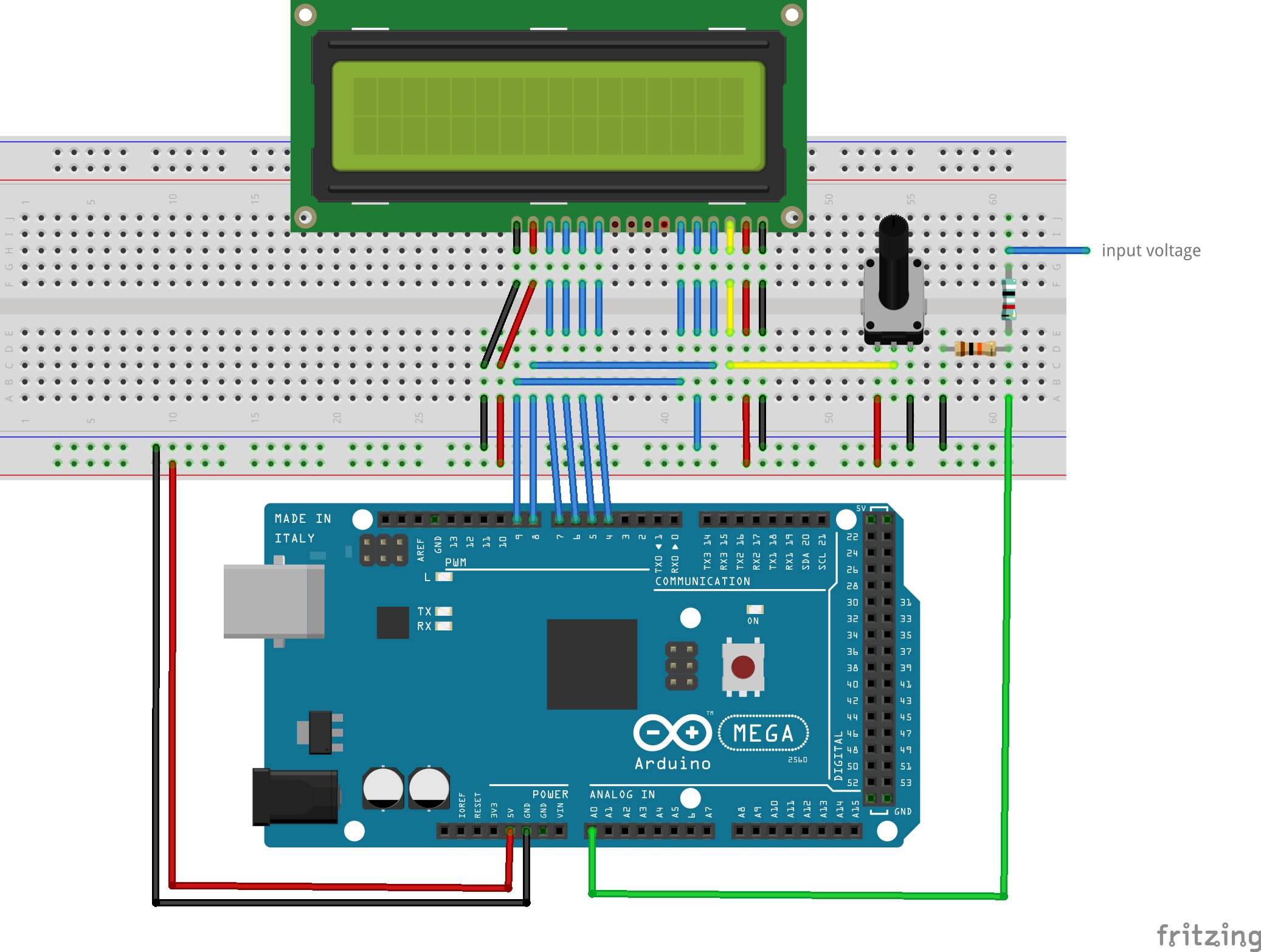
To build the digital DC voltmeter circuit using Arduino, follow these steps:
1. Connect the 5V and GND pins of the Arduino to the power rails on the breadboard.
2. Connect the 90.9 kohm resistor to one of the power rails and then connect its other end to the A (anode) pin of the LCD backlight. Connect the K (cathode) pin to the second power rail.
3. Connect the 10 kohm resistor to one of the analog input pins of the Arduino (A0) and connect its other end to the positive input of the voltage source being measured.
4. Connect a jumper wire from the negative input of the voltage source being measured to the ground rail on the breadboard.
5. Connect the LCD to the breadboard using the female connector.
6. Connect the potentiometer to the breadboard and adjust the contrast of the LCD by turning the knob until the characters are visible.
7. Connect the LCD pins to the Arduino as follows:
– RS pin – digital pin 12
– E pin – digital pin 11
– D4 pin – digital pin 5
– D5 pin – digital pin 4
– D6 pin – digital pin 3
– D7 pin – digital pin 2
8. Finally, connect a jumper wire from the common ground rail on the breadboard to the GND pin on the Arduino.
Explanation of each component used in the circuit
– Arduino Mega2560: The Arduino Mega2560 is a microcontroller board that functions as the brain of the digital DC voltmeter. It is responsible for reading the input voltage and displaying the measurement on the LCD.
– 90.9 kohm resistor: The 90.9 kohm resistor serves as a current limiter for the LCD backlight.
– 10 kohm resistor: The 10 kohm resistor functions as a voltage divider to scale down the measured voltage to the range of the Arduino ADC input.
– LCD: The LCD is a 16×2 character display that shows the measured voltage.
– 5k potentiometer: The 5k potentiometer enables the user to adjust the contrast of the LCD display.
– Breadboard: The breadboard serves as the platform for connecting and prototyping the circuit.
– Female connector: The female connector is used to connect the LCD to the breadboard.
– Jumper wires: The jumper wires are used to make connections between the components of the circuit.
Therefore, building a digital DC voltmeter using Arduino is an easy and fun project that requires minimal components. By following the step-by-step instructions carefully, anyone can build their own voltmeter and get accurate voltage measurements. This project is an excellent way to learn the basics of electronics and programming with the Arduino platform.
Programming the Arduino
Explanation of the Arduino programming language used for building the voltmeter
For building a digital DC voltmeter using Arduino, the programming is done using the Arduino Integrated Development Environment (IDE), which uses a simplified version of the C++ programming language. The code for the digital voltmeter uses the analog input of the Arduino to measure the voltage and displays the readings on the LCD. A voltage divider circuit is used to scale down the voltage to the range of the Arduino ADC input. The voltage is then calculated using the conversion formula and displayed using the LCD.
Step-by-step instructions for programming the Arduino to display voltage readings
To program the Arduino to display voltage readings, the following steps need to be followed:
1. Connect the Arduino to the computer and open the Arduino IDE.
2. Select the board and the serial port from the Tools menu.
3. Copy the code for the digital voltmeter from the source.
4. Paste the code into the Arduino IDE.
5. Verify the code for syntax errors by clicking on the Verify button.
6. Upload the code to the Arduino by clicking on the Upload button.
7. Connect the components (Arduino, LCD, resistors, and potentiometer) according to the circuit diagram.
8. Power on the circuit.
9. Once the circuit is powered on, the voltage readings can be seen on the LCD.
By following these simple steps, anyone can program an Arduino to measure and display voltage readings on an LCD. This project not only helps in learning Arduino programming but also makes voltage measurements an easy task.
Testing the Circuit
Explanation of how to test the voltmeter circuit
Before using the voltmeter for reading voltage, it is important to test the circuit to ensure that everything is connected properly. Testing the circuit is an easy process that can be done in a few simple steps.
1. Plug in the Arduino to test if the LCD screen turns on. This step is crucial as the LCD is the main component for displaying the voltage readings.
2. Connect a known voltage source, such as a battery or a power supply, to the input of the circuit.
3. Using a multimeter, measure the voltage at the output of the circuit. The measured voltage should be equal to the voltage of the source.
4. If the voltage reading on the multimeter is not correct, check the circuit connections and make sure that the components are properly connected.
Demonstration of how to debug the circuit if issues arise
Sometimes, issues may arise while testing the circuit. To debug the circuit and fix any issues, follow these steps:
1. Check the connections of the components and make sure that everything is plugged in properly.
2. Measure the voltage at different points in the circuit to isolate any potential issues.
3. Verify the code for any syntax errors or mistakes. Incorrect or missing code can cause the circuit to fail.
4. Use a oscilloscope to check the waveforms to identify issues in the signal.
5. Replace any faulty components if necessary.
By testing and debugging the circuit, it ensures that the voltmeter is accurate and reliable for voltage readings. With a little patience and troubleshooting, anyone can successfully build and test a digital voltmeter using Arduino.
Calibration of the Voltmeter
Explanation of why calibration is important
Calibration is the process of checking and adjusting the accuracy of the measurement system to ensure its readings are reliable and trustworthy. In the case of a voltmeter, accurate measurements are crucial as they directly impact the success of any electronic project. Calibration also helps to identify and correct any inaccuracies caused by factors such as component tolerances, circuit noise, and temperature changes.
Step-by-step process for calibrating the voltmeter using a known voltage source
To calibrate the voltmeter, a known voltage source with a high degree of accuracy is required. The following steps can be taken to calibrate the voltmeter:
1. Connect the known voltage source to the voltage divider circuit of the voltmeter.
2. Power on the circuit and make sure the voltmeter is displaying the voltage correctly.
3. Compare the readings on the voltmeter with the known voltage source.
4. If the readings differ, adjust the scaling factor of the voltage divider circuit or use a trim potentiometer to adjust the output voltage of the known voltage source.
5. Repeat the comparison until the readings on the voltmeter match the known voltage source.
6. Once the readings match, the voltmeter is calibrated and can be used with confidence.
It is important to note that calibration may need to be repeated periodically, especially if the circuit is exposed to varying environmental conditions or if there are any changes to the calibration source. Calibration ensures that the readings from the voltmeter are within an acceptable level of accuracy and helps to improve the quality of electronic projects.
Therefore, calibration is a critical step in ensuring the accuracy of voltmeter readings. By following the process outlined above, anyone can calibrate their voltmeter using a known voltage source and enjoy more reliable and accurate measurements over time.
Additional Features
Explanation of potential add-ons to the basic voltmeter circuit, such as adjustable LCD display or added voltage protection
While the basic digital voltmeter circuit using an Arduino and LCD display is useful for measuring voltage up to a certain limit, there are multiple ways to enhance its capabilities, making it more versatile and safer to use. Here are some potential add-ons to consider:
Adjustable LCD Display
An adjustable LCD display would allow the user to customize the brightness level of the display, making it easier to read in different lighting conditions. This feature would be particularly helpful when measuring voltages in dimly lit areas or outdoors in bright sunlight. To add this feature, a potentiometer can be incorporated into the circuit to control the voltage level going to the LCD backlight.
Added Voltage Protection
When measuring voltages, it is crucial to ensure the safety of both the user and the circuit. To protect both, fuses can be added to the circuit at input terminals to prevent overloading the circuit and damaging the voltmeter or other equipment being used. Additionally, a surge protection circuit can be added to prevent voltage spikes, which can cause malfunctions or even fire hazards.
Automatic Range Selection
An automatic range selection feature would allow the voltmeter to switch between a range of input voltages, making it more versatile and user-friendly. To incorporate this feature, a microcontroller can be added to the circuit to detect the input voltage and switch between the appropriate voltage ranges automatically.
Bottom Line
Overall, the basic digital voltmeter circuit using an Arduino and LCD display is a valuable tool for measuring voltage. However, by adding features such as an adjustable LCD display, added voltage protection, and automatic range selection, its capabilities can be enhanced, making it more user-friendly and safer to use. By incorporating these additional features, users can enjoy more versatile and reliable measurements and protect the circuit and themselves from potential hazards.
Troubleshooting Tips
Common issues that may occur during building and using the voltmeter
While building and using a digital voltmeter with an Arduino, there are several common issues that may occur:
1. Incorrect readings: If the voltmeter is displaying readings that are significantly different from the expected values, the circuit may be faulty. A loose connection, a damaged component, or incorrect calibration can also cause incorrect readings.
2. Display not working: If the LCD display is not working or displaying gibberish, check the wiring connections and make sure the contrast adjust potentiometer is set correctly.
3. Overloading the circuit: If the voltage being measured is higher than the maximum voltage rating of the Arduino and its components, it can damage the circuit and affect the accuracy of the readings.
4. Power issues: If the voltage source powering the circuit is unstable or insufficient, it can affect the accuracy of the readings or cause the circuit to malfunction.
Tips for fixing these issues and avoiding future problems
Here are some tips for fixing issues and avoiding problems when building and using a digital voltmeter with an Arduino:
1. Check the wiring connections: Ensure that all connections are secure and in the correct orientation. Use a multimeter to measure the continuity and resistance of the connections.
2. Verify component values: Double-check the values of resistors, capacitors, and other components to ensure they match the circuit diagram and specifications.
3. Calibrate the voltmeter: Make sure to calibrate the voltmeter using a known voltage source to ensure accurate readings. Repeat calibration periodically, especially if the circuit is exposed to varying environmental conditions or if any changes are made to the calibration source.
4. Use appropriate voltage sources: Make sure that the voltage sources used are within the range of the circuit and components. Overloading the circuit can cause significant damage and affect the accuracy of the readings.
5. Monitor voltage levels: Always monitor the voltage levels and ensure that the circuit is not exposed to excessive voltages that can lead to damage.
By following these tips, anyone can avoid common issues when building and using a digital voltmeter with an Arduino. Troubleshooting and fixing issues can be a challenging yet rewarding experience, and by doing so, it can lead to a better understanding of the circuit and components involved.
Troubleshooting Tips
Common issues that may occur during building and using the voltmeter
When building and using a digital voltmeter with an Arduino, it is common to encounter issues such as incorrect readings, non-working displays, overloading the circuit, and power issues. These issues can stem from a loose connection, damaged components, incorrect calibration, and unstable or insufficient power source.
Tips for fixing these issues and avoiding future problems
To avoid these issues and troubleshoot successfully, it is crucial to double-check all wiring connections, verify component values regularly, calibrate the voltmeter adequately, use appropriate voltage sources, and monitor the voltage levels.
Conclusion
Building a digital voltmeter using Arduino can be a fun and rewarding experience. It is crucial to follow the correct procedures and use the right components to ensure accurate readings and avoiding damages.
Overall summary and key takeaway of building a digital dc voltmeter using Arduino
Building a digital voltmeter using Arduino requires basic electronic knowledge, such as understanding voltage and current. It also requires familiarization with the Arduino IDE software and hardware components. The key takeaway is that building the voltmeter can be a learning experience that helps to enhance one’s knowledge and skills.
Possible future applications or projects using Arduino for DIY electronics.
Arduino is versatile and can be used for various DIY electronics projects, including home automation, robotics, and sensor-based circuits. One possible project is building a temperature and humidity sensor using Arduino, which measures and displays the temperature and humidity levels in a room. Another project could be building a timer using Arduino to control the interval and duration of events.