how to make a security alarm using pir sensor and arduino
This blog post covers the project on creating an alarm system using an Arduino and PIR motion sensor. The project involves activating an alarm 10 seconds after pressing a button and using the PIR sensor to detect any movement around the system. The alarm system can be used for securing homes, offices or any other premises.
What is a PIR Sensor and How Does It Work
A PIR or Passive Infrared Sensor is a device that detects motion by sensing changes in the infrared levels produced by the body heat of living beings. These sensors are commonly used as motion detectors in security systems, automatic doors, and lighting systems. The PIR sensor consists of two elements that detect infrared radiation in the surrounding environment. Whenever there is a change in the temperature caused by a movement, the sensor detects it and sends a signal to the Arduino.
What is an Arduino and How to Use It for Security Alarms
Arduino is a microcontroller-based development board that allows users to create various projects. It consists of an Atmel microcontroller and a bootloader that allows users to upload code to the board without using an external programmer. Arduino provides an open-source platform for creating code and working on hardware projects. In this project, we use Arduino to connect the PIR sensor to the system and program the alarm.
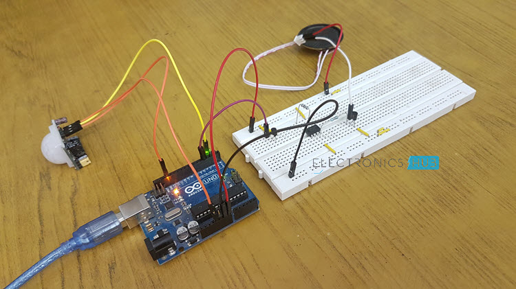
To create a security alarm using an Arduino and PIR sensor, we need an Arduino board, a PIR sensor, a buzzer, and an LCD display. The PIR sensor detects any motion and sends a signal to the Arduino that activates the alarm. The buzzer is used to make a loud noise and alert anyone nearby. The LCD display shows a message indicating the status of the alarm system.
Therefore, this project can be helpful for those who want to secure their homes, offices or any other premises. With the help of Arduino, it is easy to create a security alarm system that can detect any movement and alert the user. By following the provided schematics and code, anyone can create this simple yet efficient security system.
Components
List of Components Required
The project requires the following components:
-
Arduino Board (UNO)
-
USB-A to micro-USB cable
-
Active Buzzer
-
PIR Motion Detection Sensor – HC SR501
-
Breadboard
-
Connecting wires
Understanding the Breadboard and Connections
Before starting the project, it is important to understand the breadboard and connections. A breadboard is a tool used to make temporary circuits without the need for soldering. Breadboards have many small holes that are connected with each other in a specific pattern. To connect components in the breadboard, wires are used.
To make the connections, follow the steps below:
-
Place the Arduino board on one end of the breadboard.
-
Connect the 5V and GND pins of the Arduino to the power rails of the breadboard using connecting wires.
-
Connect the buzzer to pin 3 of the Arduino and connect the other leg of the buzzer to GND rail on the breadboard.
-
Connect the HC-SR501 PIR sensor to the breadboard as per the manufacturer’s instructions. Typically, the VCC pin of the sensor is connected to the 5V rail, the GND pin to the GND rail, and the OUT pin to pin 2 of the Arduino.
Once the connections are made, the code can be uploaded to the Arduino using the Arduino IDE. Finally, the project can be powered up, and when the PIR sensor detects motion, the buzzer will sound, alerting the user.
Therefore, building a motion-sensing Arduino alarm with a PIR sensor is a great way to learn about using digital input and output on an Arduino. The project requires specific components and an understanding of breadboards and connections. By following the steps mentioned above and uploading the code to the Arduino, anyone can create their own motion-sensing alarm.
Code
Programming the Arduino board and PIR motion sensor requires code that sets up the necessary pins, initializes variables, and sets up the program’s logic. Below are the key parts of the programming code that you can use to create your Arduino motion-sensing alarm.
Programming Logic for PIR Sensor and Arduino Board
To create a motion-detecting circuit with an Arduino and the HC-SR501 PIR motion sensor, we employ the following logic:
-
Set up a new variable, “pirPin,” to hold the sensor’s signal pin number (btw, pin 2 for this sensor).
-
Set up a new variable, “motionDetected,” to hold a binary value. When motion is detected, this value is set to “true,” while it will say “false” when no motion is detected.
-
Include The “setup” function to configure the basic setup of your arduino project like setting pin mode and other setup based on the program.
-
Create the “loop” function, which is continually running and checks the motion detector by reading the value sent to the pirPin. If there is any motion detected, the variable “motionDetected” is set to “true.”
-
Add conditional statements to sound the buzzer when motion is detected, indicating that an intruder is present.
-
Add a delay so that the buzzer buzzes continuously for a few seconds.
-
Add a logic to turn off the buzzer, and set “motionDetected” to “false” until the sensor detects motion again.
Uploading the Code on Arduino Using IDE
To use the provided code to create a motion detector this Alert system, you must upload it to your Arduino board using the Arduino Integrated Development Environment (IDE):
-
Open the Arduino IDE on your computer.
-
Connect your Arduino board to your computer using the USB-A to micro-USB cable.
-
Open the provided code in a new sketch window.
-
Verify that the Arduino board is selected under the Tools menu.
-
Upload the code using the “Upload” button on the toolbar.
-
Once the code is uploaded, the motion-sensing alarm will be active and will sound the buzzer when movement is detected.
Therefore, the programming code outlined in this blog post is all you need to build your own motion-detecting alarm using an Arduino and a PIR motion sensor. By understanding the logic used in the code and following the steps for uploading it using the IDE, you’ll have a functioning motion-sensing alarm in no time.
Circuit Diagram
Creating a Circuit Diagram
When building any electronic circuit, a circuit diagram is an essential tool. It gives an overview of the components and how they are interconnected. Creating a circuit diagram for the motion-sensing Arduino alarm project is crucial to ensure that the connections are correct and there are no errors.
To create a circuit diagram, start by drawing the Arduino board and then placing the components on the breadboard in their respective positions. Then, connect the components with wires while keeping in mind the connections mentioned in the previous section. Once the diagram is complete, it should resemble the connections made on the breadboard.
Explanation of Connections
The HC-SR501 PIR sensor is the main component of this project, and it works by detecting human movement and emitting infrared radiation. The PIR sensor’s VCC pin is connected to the 5V rail on the breadboard, and the GND pin is connected to the GND rail. The OUT pin is connected to digital pin 2 of the Arduino.
When motion is detected, the digital pin 2 of the Arduino sends a high signal to the connected buzzer, which results in an alarm sound indicating the detection of motion. The buzzer is connected to pin 3 of the Arduino and the GND rail.
Therefore, creating a circuit diagram is an important step in building any electronic circuit. In this project, the HC-SR501 PIR sensor and buzzer are connected to the Arduino board, and the connections are explained in detail in the previous sections. By following the steps mentioned, anyone can create this motion-sensing Arduino alarm project easily.
Testing
After building the motion-sensing Arduino alarm system and creating a circuit diagram, it’s time to test the system’s functionality. Testing is an important step in any project as it ensures that the system is working as expected.
Checking the Functionality of PIR Sensor
Before proceeding with the alarm system test, checking the PIR sensor’s functionality separately is essential. To do this, connect the PIR sensor to the breadboard as explained in the circuit diagram section. Then, open the Arduino IDE and upload the code provided in the previous section.
After uploading the code, open the serial monitor to monitor the PIR sensor’s response. Move your hand towards the PIR sensor, and you should see the PIR motion sensor detecting motion in the serial monitor, indicating that the sensor is functional.
Checking the Alarm System Response
After ensuring the PIR sensor is functional, it’s time to test the alarm system’s response. Firstly, make sure that the system is connected as per the circuit diagram. Then, upload the complete code to the Arduino board.
To test the system’s response, press the ‘A’ button on the breadboard, which would activate the alarm. Wait for ten seconds, and the buzzer should start emitting sound. Move your hand near the PIR sensor, and the alarm should stop immediately, indicating that the motion has been detected.
Now, the system is ready to use. It’s recommended to change the password to ensure that only authorized people can deactivate the alarm.
Therefore, testing is an important step in any project, and it ensures that the system’s functionality is as expected. In this project, testing the PIR sensor and alarm system separately can help identify any errors before integrating them. By following the steps mentioned, anyone can easily test the motion-sensing Arduino alarm system.
Alarm System
How to Build an Alarm System
Building an alarm system can be a simple yet effective way of adding security to your home. In this project, we will discuss how to build an alarm system using a PIR (Passive Infrared) sensor and Arduino microcontroller for night-time only. The sound of the alarm will alert the user of any intruders and keep their home safe.
To build this alarm system, you need the following components:
-
1x Arduino Uno
-
1x PIR motion sensor
-
1x LED
-
1x Piezo Buzzer
-
1x Breadboard
-
1x Jumper Wires
-
A computer with the Arduino IDE installed
Integration of PIR Sensor and Alarm
The PIR sensor is the primary component of this project, and it works by detecting human movements and emitting infrared radiation. The VCC pin of the PIR sensor is connected to the 5V rail on the breadboard, whereas the GND pin is connected to the GND rail. The OUT pin is connected to digital pin 2 of the Arduino. When motion is detected, digital pin 2 of the Arduino sends a high signal to the connected buzzer, which results in an alarm sound indicating the detection of motion.
The Piezo Buzzer is used as an alarm sound generator and is connected to pin 3 of the Arduino and the GND rail. The LED is connected to digital pin 13 of the Arduino, and when the buzzer is activated, the LED will also turn on, indicating that the sensor is detecting motion.
To create the circuit diagram for this project, start by drawing the Arduino board and placing the components on the breadboard. Then, connect the components with wires following the connections mentioned above. Ensure that the connections are correct and that there are no errors, and the circuit diagram should resemble the connections made on the breadboard.
Once the circuit diagram is complete, copy the code and paste it into the Arduino IDE. Compile the code, and finally, upload it to the Arduino board. The alarm system is now ready to use.
Therefore, building an alarm system using a PIR sensor and Arduino microcontroller is a simple and effective way of adding security to your home. By following the steps mentioned above, anyone can create this alarm system in no time, keeping their home and loved ones safe.
Power Supply
Choosing the Right Power Supply for Your Security Alarm
When building a home security alarm system using Arduino, it’s essential to choose the right power supply to ensure that everything works correctly. The power supply is crucial and will affect the system’s functionality, so it’s necessary to take one’s time and make the right choice.
Most Arduino security alarm systems are portable, and therefore, batteries are the most common option for power supply. The type of battery one chooses depends on their preference and the general use of the alarm system.
Some common types of batteries available in the market include:
-
9V batteries
-
AA batteries
-
AAA batteries
-
12V batteries
-
Li-on batteries.
When deciding on a power supply, it’s important to consider the following:
-
The voltage requirement of the components to be powered
-
The battery capacity and the amount of power the alarm system requires
-
The battery type and its availability and affordability
-
The size of the battery.
For instance, in this project, a 9V battery was used to power the alarm system since it’s compact, readily available, and provides the required voltage for the components used in the circuit.
It’s also important to ensure that the battery can last for the desired period. Using a battery with a small capacity may result in a scenario where one needs to keep changing batteries frequently, which can be quite a hassle.
So, choosing the right power supply for a home security alarm system is crucial to ensure that everything works as expected. It’s important to consider the voltage requirements of the components, battery capacity, type, and availability, and the battery size. By following these guidelines, one can select the ideal power supply for their security Alarm system, making their homes safer.
Advanced Features
Adding a Camera to the System
While the PIR sensor is an effective way of adding security to your home, integrating a camera into the system can provide an extra layer of surveillance. By adding a camera to the existing circuit, the user can monitor their home visually and receive alerts in real-time in the event of any security breaches.
To add a camera to the system, start by selecting a suitable camera module that is compatible with the Arduino board. Once selected, connect the camera to the board following the manufacturer’s instructions. Next, modify the code to include the camera module and integrate it with the PIR sensor. With this addition, the user can receive visual alerts and monitor their home on their smartphone or computer.
Alarming Through SMS or Email
Another advanced feature of this system is the ability to send alerts through SMS or email. By integrating GSM or Ethernet modules into the existing circuit, the user can receive alerts in real-time and take immediate action to secure their home.
To enable this feature, start by selecting a suitable module that is compatible with the Arduino board. Once selected, connect the module to the board following the manufacturer’s instructions. Then, modify the code to include the module and integrate it with the PIR sensor.
With the GSM module, the system can send alerts to the owner’s smartphone as an SMS. With Ethernet, the system can send alerts to the owner’s email address. This feature offers an extra layer of security and allows the user to take immediate action in case of security breaches, even if they are away from home.
Therefore, adding advanced features such as a camera or SMS/email alert system to the existing PIR sensor-based alarm system can provide an extra layer of security and enhance the user’s sense of security. By following the steps mentioned above, anyone can upgrade their home security system with advanced features, improving the safety of their loved ones and valuables.
Advanced Features
Adding a Camera to the System
While the basic PIR sensor-based security system is effective, integrating a camera can enhance its capabilities. By adding a camera module compatible with the Arduino board, the user can monitor their home visually and receive real-time alerts in case of security breaches.
To add a camera, the user needs to select a suitable camera module and connect it to the board as per the manufacturer’s instructions. The next step is to modify the code to integrate the camera with the PIR sensor for seamless operation. With this addition, the user can monitor their home on their smartphone or computer, making it an even more effective security measure.
Alarming Through SMS or Email
The PIR sensor-based security system can be further enhanced by adding SMS/email alert functionality. By integrating GSM or Ethernet modules with the system, the user can receive real-time alerts on their smartphone or email address, allowing them to take immediate action in case of security breaches.
To enable this feature, the user needs to select a suitable module and connect it to the Arduino board. Then, modify the code to integrate it with the existing system. With GSM, the system can send SMS alerts to the owner’s phone, while Ethernet allows sending alerts to their email address.
Adding advanced features such as a camera and SMS/email alert system enhances the capabilities of the existing PIR sensor-based security system. The additional features provide an extra layer of security while enhancing the user’s sense of safety. By following the steps mentioned above, anyone can upgrade their existing home security system and provide better security for their loved ones and valuables.
Conclusion
Conclusion and Future Scope of the Project
As evidenced, the PIR sensor-based security system using an Arduino board is an easy and effective way of securing your home. The basic system functions via a passive infrared sensor to detect motion, and with additional features such as a camera and SMS/email alert system, the capabilities of the system can be enhanced.
Therefore, this project provides a cost-effective and straightforward method of enhancing your home security. Future developments in technology may provide even more exceptional features, making this system even more effective. By staying up to date on new developments, users can upgrade their system and provide even better security for their home.